Wednesday, 27 March 2019

ACS 800 encoder error #7301

Here at my job we have an ACS800 multidrive to control speed and torque of the hoist motor. This post is about the error code #7301 "encoder error" and the adventure it was trying to tackle it. This is done with the aim that some of the information here may be of good use to anyone dealing with this error.
First of all, if you are reading this in desperation because the encoder error trips your winder, here I have great news: you can change the error status from FAULT (default setting) to ALARM. It can be done using drive Windows software or through the keypad as well. Doing this will give you the extra time you need to perform troubleshooting without delaying / stopping operations. Off course, to take this decision you first have to evaluate it doesn't compromise safety of operations.

Here are the steps to follow when using Drive Windows:
1. Connect to drive.
2. Open parameters window. Go to parameter 50.
3. Double click on encoder. A little window will pop up where you can choose error status to be FAULT or ALARM. Click on ALARM then click OK and that's it.


Additionally, you may like to visit the following links since they may give you ideas about how to perform troubleshooting. It worked for me.


Now, this is my adventure with encoder error #7301...

This error has been showing up occasionally since the hoist commissioning (once per month as much) but lately it's been occurring more often (1 or 2 times per day) so we decided to allocate some time to check up the reason for this fault to occur.

Error 7301

According to the ACS800 troubleshooting, this error requires to check encoder wiring. Specifically the one attached to the motor's back since its signals go from the encoder to the AHC panel and then to the RTAC module at the drive control cabinet. 

So we did it, Wiring and connections were checked and tightened. We got a couple of days error free but then it started to show up again and -lucky we- it happened at peak hour. We changed the error status from FAULT to ALARM to give us chance to finish the shift and continue with troubleshooting.
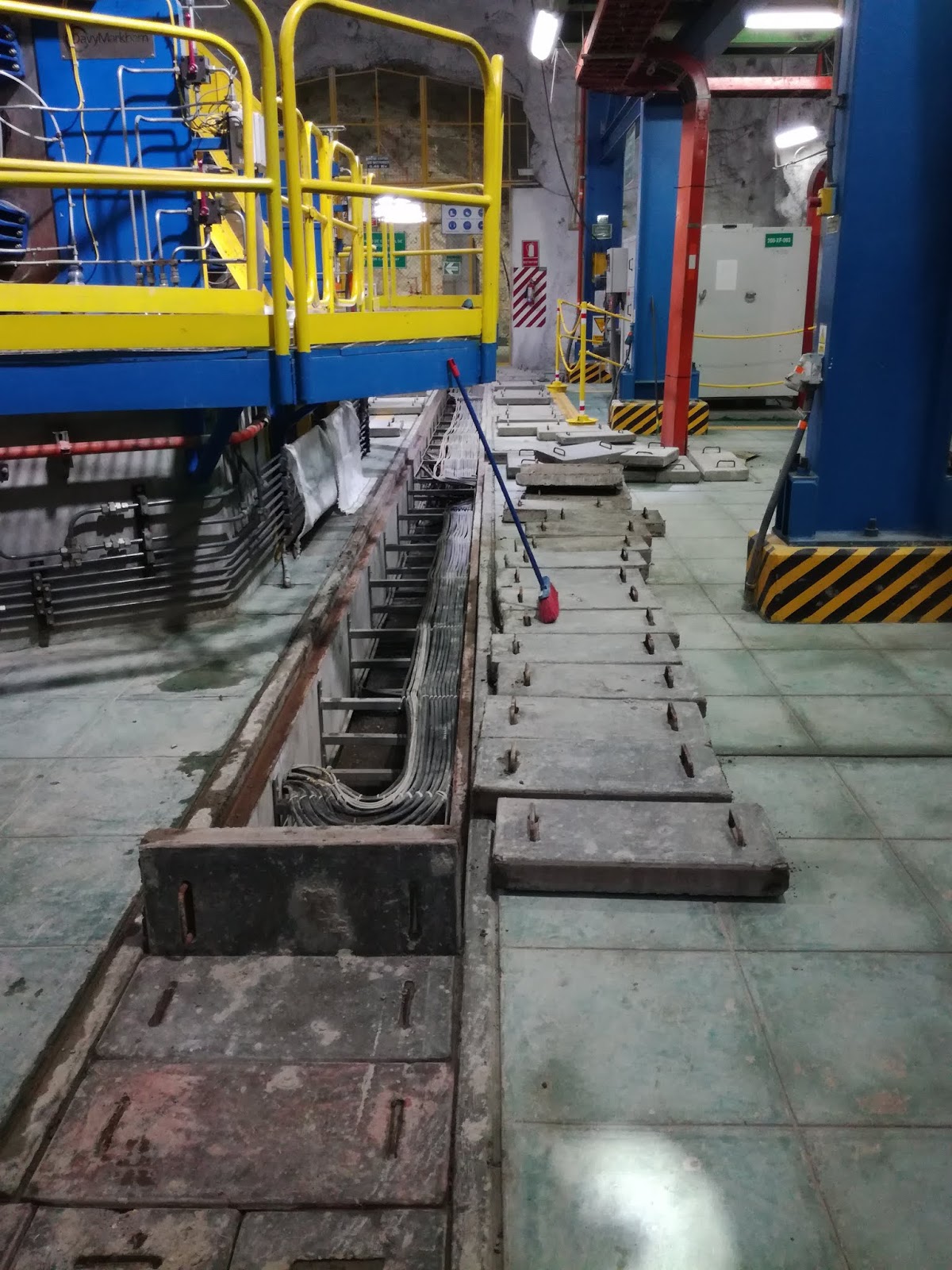
Wiring check up at both ends and through cable tray


Next steps were made to determine which element was causing us headaches:
* Change encoder: no results.
* Change of Isolation amplifier card PE1315A at AHC: No results.
* Change of RTAC module: Error free for a week then it started again.
* Change encoder wiring from encoder to junction box: no results. Here we noticed that motor cover was deforming the wiring so we asked our mechanical people to modify it as a preventive measure despite it was not the cause of the fault.


* Change of encoder wiring from junction box to AHC panel: no results.
* Change of encoder wiring from AHC panel to RTAC module at drive: Eureka! We believe this wiring was damaged during installation.

Thursday, 16 August 2018

Shaft guide alignment using a decelerometer

I work in an underground gold mine in the north of Darkest Peru. The company has recently commissioned an 800 metres long vertical shaft with the purpose to transport personnel, material and waste. It has four compartments, two for skips and other two for a cage and its counterweight. Since it was a new shaft we thought everything was in good working conditions but it wasn't the case because we found that there were friction between skips and their metallic guides in several locations along the shaft. This was causing rapid wearing of skips' roller guides (We had one roller guide completely worn out after just three days). There even were some places where friction was strong enough to produce sparks.

This situation frightened the mine's management people so experts were hired to look at this problem. Few days later we got the visit of two guys from Tiley Associates who performed a shaft guide alignment test using a decelerometer. The idea of the test is to correlate acceleration measurement vs shaft's depth. Places with high acceleration measurement are an indicator of guide missalignment. The following criteria is used to determine wether the situation is critical or acceptable.
  • Critical guide missalignment: acceleration measurement is greater than 0.5g or lower than -0.5g. Requires to take immediate corrective action.
  • Bad missalignment: acceleration measurement between -0.5g and -0.25g or between 0.25g and 0.5g. Corrective action should be scheduled during the next planned maintenance.
  • Acceleration between -.025g and 0.25g can be taken as acceptable missalignment.
Note 1: This criteria is valid under the consideration that shaft's structural integrity is in good conditions. 
Note 2: g=9.8m/s2.

Our technicians used the information from the Tiley report to improve guide alignment and results started to show immediately: Smooth cage and skips movement, no sparks and a significant reduction of guide rollers wearing. With these results in mind, our company decided that alongside periodical Tiley assessment we should perform an internal assessment more often so any problem can be spotted while it is in its early stages. For that to be done a decelerometer has been bought. In matter of weeks we developed a template in excel that uses raw input data from decelerometer and shows acceleration vs depth which is valuable information when performing shaft inspection.

Raw data from decelerometer is given in the following format:

Station_code    GMS
Sampling_rate   50.000000
Start_date      23.05.2018
Start_time      18:10:35.000
Time:sec   X0HNE,g    Y0HNN,g    Z0HNZ,g
0.0000000000e+00 6.7869942000e-04 6.1697539000e-04 4.8637476000e-04
2.0000000000e-02 6.2969107000e-04 6.0955791000e-04 5.4756897000e-04
4.0000000000e-02 5.9445804000e-04 6.0002115000e-04 5.5737064000e-04
6.0000000000e-02 7.1790610000e-04 5.6717231000e-04 5.1789905000e-04
8.0000000000e-02 7.4996021000e-04 5.8041781000e-04 5.1339558000e-04
1.0000000000e-01 6.1141228000e-04 5.5710573000e-04 5.6372848000e-04
(...)

First 4 rows show information of the station, date, time and sampling rate. From the 5th row we can notice withdrawn data from the station: Time vector and gravity acceleration in X, Y and Z axes.

g vs depth graph

X and Y axes give information about lateral movement of skips along the shaft while Z axes provides vertical acceleration. Speed and position can be obtained by integrating and double integrating acceleration values. Some help and guidance can be found in this Wikihow post.

Knowing alignment conditions beforehand allowed us to do inspections in less time and saved us thousands on rollers replacements so implementing this activity is highly recommended.


Tuesday, 4 August 2015

Nanosecond pulse generator

Well, where to start... A nanosecond pulse generator is used as part of an experimental space charge measurement equipment developed at the UNSW's High Voltage Laboratory. The required output must provide not only a narrow width (less than 15 ns) but also a magnitude that exceeds 200 V (the goal was 500V). Most of the literature available regarding nanosecond pulse generators is related to biomedical applications, e.g. Sanders et. al, [1] have developed a pulse generator to deliver electric fields to biological loads in order to produce cellular membrane  electropermeabilization. Pulse generators of this type (relatively high magnitude, short duration) are being used in other applications within four major categories [2]: 

  • Industrial: food processing, concrete recycling, plasma systems.
  • Environmental: ozone generation, waste water treatment.
  • Medical: electroporation, plasma medicine.
  • Military: laser guns, electromagnetic launchers, radars.

Nanosecond pulse generators are available in the market but they are yet expensive, especially for research and educational activities. The cost of a single pulse generator with the required characteristics can go well beyond 4000 USD. AV Tech pulse, FastPulse technology Incorporated, Yamabishi Corporation, FID GmbH are among the companies specialized in providing this type of equipment. 

Some of the most important topologies are:
  1. Diode opening switch (D.O.S): this topology generates a clear and well defined pulse, however the calculation of the components is complex as well as its implementation since it depends on several parameters such as the reverse recovery time of the diode, the MOSFET’s linear behaviour and the spurious triggering in the PCB layout [1].
  2. Marx Bank based pulse generators: They are usually big in size and their implementation require spark gaps that may lead to high jitter. There is a variation of the topology called miniaturized Marx Bank which use transistors instead of spark gaps [3].
  3. Transmission line based pulse generators: self-matched transmission line Blumlein [4] provides fast rise time and a square shaped pulse [5].

The first topology had been chosen due to its simple circuitry and was successfully implemented by Wu Chao [6] based on the work exposed in [1]. My first task was to make copies of the existing pulse generator but changing the pulse width in order to see if the pulse width has a significant impact on the measurement results. Unfortunately, Wu Chao had already graduated by the time I was doing this project so I had no have chance to bother him with questions. After reading his work, I decided to simulate the circuit using LTSpice, this was crucial for me to understand how this topology works so I think it is worth to share it. It does not have the same components used at the end but it gives a good approximation of the result. The main component is the diode D1 since the pulse width and the selection of C1,C2,L1 and L2 values depends on the reverse recovery time of the diode [1].

Simulation circuit of the pulse generator using LT Spice. Stop time=0.1s.

Simulation result of the pulse generator circuit using LTSpice. The pulse output can be noticed in blue in the bottom panel.
After few weeks, a couple of pulse generator boards were made, they are capable to provide a pulse width of 13 ns (full maximum half width method) with a magnitude of 250 V.

Pulse generator boards. Courtesy of  UNSW's High Voltage Laboratory.

Pulse output. Courtesy of  UNSW's High Voltage Laboratory.

References
[1] J. M. Sanders, A. Kuthi, W. Yu-Hsuan, P. T. Vernier and M. A. Gundersen, “A linear, single-stage,nanosecond pulse generator for delivering intense electric fields to biological loads,” IEEE Transactions on Dielectrics and Electrical Insulation, vol. 16, pp. 1048-1054, 2009.
[2] S. Zabihi, Flexible high voltage pulsed power supply for plasma applications, Brisbane: Queensland University of Technology , 2011. 
[3] M. Inokuchi, M. Akiyama, T. Sakugawa, H. Akiyama and T. Ueno, “Development of Miniature Marx Generator Using BJT,” IEEE Pulsed Power Conference, pp. 57-60, 2009. 
[4] S. Romeo, C. D’Avino, O. Zeni and L. Zeni, “A Blumlein-type, Nanosecond Pulse Generator with Interchangeable Transmission Lines for Bioelectrical Applications,” Transactions onDielectrics and Electrical Insulation, vol. 20, no. 4, pp. 1224-1230, 2013.
[5] G. Peng, Design of a modular high voltage nanosecond pulse generation system, Sydney: The University of New South Wales, 2013.
[6] C. Wu, Space Charge Measurement in Solid Dielectrics, Sydney: UNSW, 2012. 

Sunday, 2 August 2015

USB atmel programmer

Back in time, when I was an undegrad student, I used to have an Atmel programmer with a parallel connector. Happiness was endless burning micro controllers one time and another, until I upgraded my old but loyal desktop PC for a fancy laptop. I won't lie, I get used to the laptop rapidly with not even a minor remorse about leaving my PC aside. However, the laptop did not have a parallel port. But it was plenty of USB ports, so my first option was to get a parallel-to-USB adapter but just before that happened I lent my programmer to a friend and that fellow has not show up till now. Months later, I looked for a way to make my own programmer to satisfy my thirst of doing electronics and got to the website of Thomas Fischl and his USBasp (http://www.fischl.de/usbasp/) which was simple and cheap. Within a few days I got the components, spent some time doing the routing in Eagle and voilá! a USB programmer was ready to be used... well it was not that easy, the USBasp uses a ATMega8 to deal with the communication protocol between the computer and the device to be programmed. So basically I was in need to use another programmer to burn the code into the ATMega8. Happily for me, there were some spare programmers at my uni that I can borrow. Once that was complete the rest was only the installation of the firmware and a software(eXtreme burner) to write/read into the microcontroller which I also got from Fischl's website.

There are a couple of jumpers in the circuit proposed by Fischl. they allow clock selection (JP1) and self programming (JP2). In my case, JP1 is connected to ground and JP2 had left open since I was not using those features.

Here is my programmer, it is more than 3 years old and it has been used in Peru and now is helping me to do some tasks during my masters studies in Australia. I hope you guys can also enjoy your free time doing some cool stuff using this programmer. If you feel a bit lazy or wanna go safe, the USB programmer can be purchased from Thomas' website.


Thursday, 2 July 2015

First post

Hello!

I am very happy to make this first post. I always wanted to start a blog where I can show and share some of the projects I do in my spare time and now is the time to make it happen! I hope the information here can be useful.

Jose